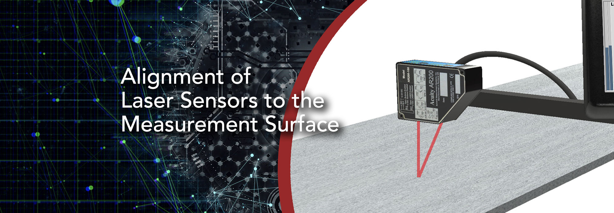
Alignment of Laser Sensors to the Measurement Surface
Proper Sensor Alignment and Fixturing is Crucial for Accurate Results
Acuity sensors should be carefully mounted and aligned in order for your application to receive optimum results. Every one of our sensors has precision mounting holes that can be used with fixturing to mount and align the sensor bodies. The following guidelines will produce the best results for your application.
Alignment to the Measured Dimension
The most important consideration to reduce measurement error is aligning the sensor beam so that it is parallel to the dimension to be measured.
The easiest example to describe is height. If you wanted to measure the height of an object with a ruler, you would want that ruler to be perfectly up and down. If the ruler weren’t perfectly up and down, you’d expect an error with your measurement. It’s the same with the laser beam on our sensors. You’d ideally want to align the beam so that it is perfectly up and down to measure height. Any deviation from that alignment would introduce an error in the measurement.
While truly perfect alignment is impossible, with care and a well-made fixture or alignment bracket, you often can get the alignment accurate enough to reduce the alignment error to significantly less than the sensor’s error. At that point, you may be able to disregard that error altogether.
If your application does not allow you to align the sensor this way, please see the “Correcting Known Alignment Errors” section toward the end of this document.
Alignment to the Target Surface
You must align the sensor dimensionally or correct for misalignment to get a decent measurement, but the angle between the beam and the surface of the target can also be a source of error.
Ideally, you want the laser beam of the sensor to strike the target surface as close to perpendicular as possible. There are a few reasons for this.
First, while the laser spot from our sensors often looks like a single point on the target, it does have a diameter. The more angled the target is, the more the spot stretches out on the target. This does make it more difficult for the sensor to know where the center of that spot is, and that can cause errors.
Second, an angled target will usually reflect more light away from the sensor’s detector. The less light the detector gets, the harder it is for the sensor to distinguish the measurement from other light noise. That can reduce the measurement accuracy, increase the measurement time, or both. This problem increases with the shininess of the target.
Third, an angled or rough target that is shiny can cause the opposite problem — direct reflection into the detector. Our triangulation sensors rely on a diffuse reflection from the target. They “see the spot” and use that to calculate the distance. This results in a peak in a predictable location on the detector relative to the target’s distance. If there is “specular” or direct reflection, that shows up on the detector as a second peak that has no relation to the distance. This can result in measurements that are completely incorrect or keep the sensor from offering a measurement at all.
While this can be a show-stopper in the worst case, it’s usually just another matter that should be considered when integrating laser sensors into your application to improve results. If you have an application where the orientation of targets will vary, taking steps to reduce that variation will help reduce the possibility of problems.
Orientating Laser Sensors
For some applications, it is important to understand how to orient the laser sensors for best results.
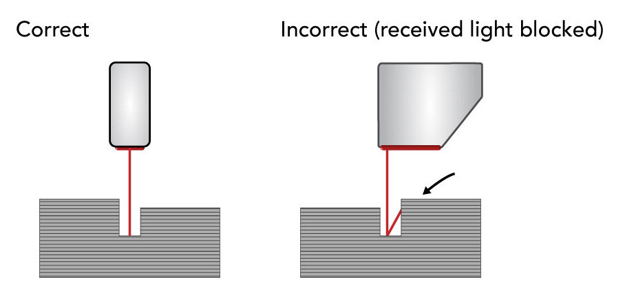
For Measurement Across an Uneven Profile or in a Tight Narrow Space:
It is important to not block the laser beam or the view of the laser detector. For applications where the target has indentation, troughs, or other features that span the width of the surface, the sensor can be oriented to avoid those features blocking the detector. By mounting the sensor so its length is parallel to the feature, you can help avoid missed measurements. See the diagram below for a visualization.
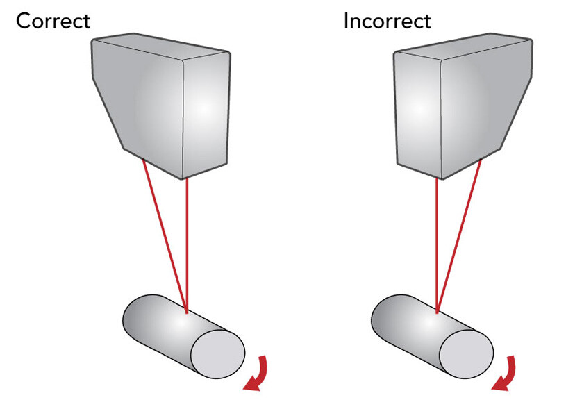
For Measurement of Rolling Objects or Curved Objects:
Laser sensors can also be used to measure curved rolling targets. For best results, mount the sensor as shown in the below graphic with the length of the sensor perpendicular to the curve (or parallel to the length of a cylinder). The beam should be positioned facing directly toward the center of the curvature. This should eliminate any tilt seen by the laser. In addition, this will reduce the likelihood of an errant direct or specular reflection or an obstruction from the curvature.
Correcting Known Alignment Errors
Sometimes it is too difficult or costly to align a sensor to near perfect accuracy. If you find yourself in this position, you can correct for an alignment error with what we call a 2-point calibration. If you have our Touch Panel Display, it can walk you through the process, but if you don’t, don’t fear! The process is simple.
If you have a misaligned sensor, the difference between two different measurements won’t be correct, but they will be wrong by a constant factor, so all you have to do is divide by that factor to correct it. How do you find that factor? Don’t worry about breaking out the protractor and trigonometry book. It’s easier and more precise to let the sensor measure it using two targets of known size.
Let’s take the height example again. You’ve set up the sensor, but you have to set it at a bit of an angle to get it around a piece of machinery. To get the error factor, all you have to do is measure two objects of known height, take the difference of the measured heights, and divide by the difference of the actual heights. For example, if you had measured two boxes to have heights of 12 cm and 24 cm, but you knew that they were 10 cm and 20 cm high respectively, the error factor would be (24-12)/(20-10) or 1.2. Now for any other object, you only need to divide the measurement by 1.2 to get the true height as long as a) the sensor doesn’t move, and b) the beam is always striking the highest point of the target.
This correction does introduce error due to the fact that there is an error in the known measurement of the objects, so it is best to perform this type of calibration with gauge blocks or other objects that have their measurement errors certified by trusted standards (e.g. “NIST traceable”).
Alignment Of Dual Opposing Sensors Is Critical
Lastly, when making dual thickness measurements with laser sensors, it is important to align the sensors’ beams as well as take and process measurements from both heads at the exact same time. For precision thickness applications, it is imperative that the sensors are aimed directly opposite to each other. For more on this, please read Synchronizing Dual Laser Sensors For Thickness Measurement.
DO YOU HAVE A CHALLENGING APPLICATION?
Our sales team has decades of experience in the field finding solutions for our customers’