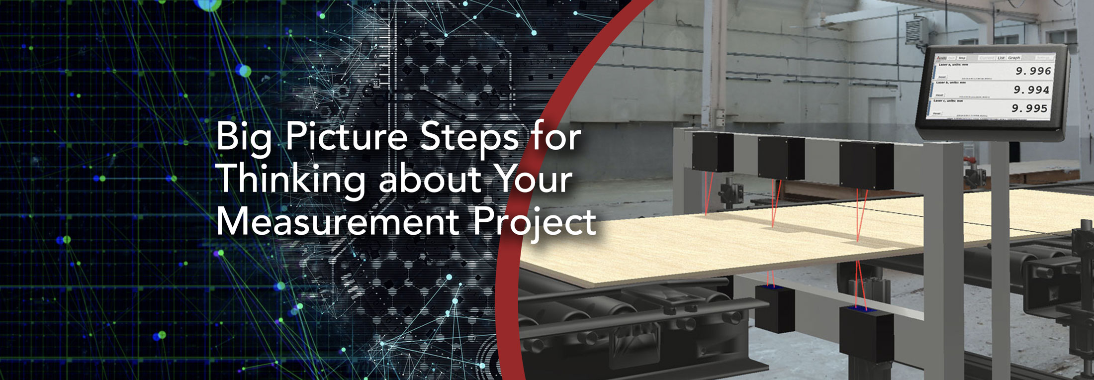
Big Picture Steps for Thinking about Your Measurement Project
How to Avoid Common Pitfalls in Measuring with Laser Sensors
Will they work for me?
Many companies have used Acuity sensors to make their business more precise, predictable, and profitable, but everything has its strengths and weaknesses. If you’re new to laser measurement sensors, you’re likely to have one big question: will they work for me?
To help you answer that question, I’d like to ask some introductory questions. Below are a few of the big picture scenarios you should put in front of yourself when thinking about using laser sensors in your project. These questions will give you an idea about how to evaluate your needs and help you determine if laser distance measurement is right for you.
What are you measuring?
That sounds like a simple question, but the answer needs to be both specific and complete. Let me take an example that’s pretty common: measuring the thickness of a plywood sheet.
First, think about the plywood surface. What does the surface look like? Is it dark or light colored? Is it rough or smooth? Is it matte or shiny? Is there a clear protective coating?
Then, think about the plywood itself. Plywood is famously opaque, but are there holes where light could get through? Plywood is also pretty rigid, but is there a possibility of it flexing as it’s measured?
It’s important to describe the target of your measurements to yourself as thoroughly as you can. Then you can best determine how compatible it is with a laser distance sensor. Here’s a handy table:
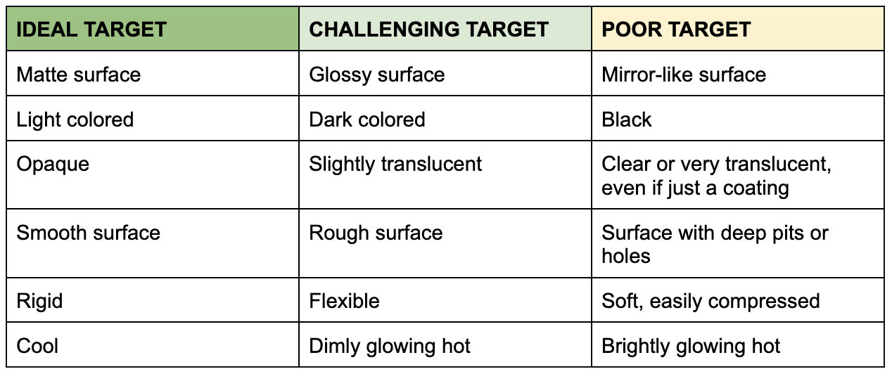
Let’s break this down:
- An ideal target is likely to be able to be measured accurately at the limits of the sensor’s measurement speed without much worry about analyzing and correcting the data afterwards.
- A challenging target is still likely to give good results, but there may be a tradeoff between accuracy and speed, and the data might need a little work to be useful.
- A poor target will likely have accuracy and speed degradations in the best case or may not be measurable at all in the worst.
In our example, plywood is usually matte, light colored, opaque, rigid, and certainly not glowing hot. It can be a little rough, so you may want to ensure you are considering the peak thickness of a section of the sheet. That said, if it has a clear coat on the surface, that could cause problems.
As you can see, there are a lot of properties that need to be considered to know if a target will work, and it’s important to start by considering them as completely as possible. This will start to give you a picture of how well an Acuity sensor may work for you.
What do you need?
So, your target is a good match. Great! Now, let’s talk about what you’re looking to get out of your measurements. Speaking to customers over the years, I have often found a big difference between what a customer wants and what that customer really needs.
There is a concept I call the Best Worst Acceptable (BWA). The BWA is right at the edge of where you’ll be unhappy. That’s the point where performance meets affordability, and it’s the point where our sales team can start helping you find specifications you can live with. Once you know that, there might be opportunities within your budget to do better.
You should ask yourself the following questions, keeping in mind your BWA for each:
- What accuracy do I need?
- How many measurements do I need in each direction?
- How often do I need measurements?
Let’s take our plywood example and answer those questions. The sheets you’re looking to measure are 4 foot by 8 foot and have a thickness of 3/4th of an inch. I know there are some interesting measurement conventions in the lumber industry, but I’ll take these measurements literally. A typical tolerance is 1/64th of an inch (0.016” or 0.4 mm), but you’ll want an error of at least half that to give room for the error that vibration or other environmental factors might cause. So your BWA error might be 0.008”.
In this case, you’re in luck. An AR200-50 has a linearity error of 0.002”, and when used as a pair for measuring thickness, the total linearity error is 0.004”, one half of the error you’re looking for!
But now we need to consider how many measurements you need on the plywood sheet. Again, start with your BWA. Let’s say the sheets move on a conveyor at a foot per second lengthwise. Previously, workers would pull a sample every 100 sheets or so and measure 5-10 points on the sheet to verify the thickness.
You know from past experience that the surface on the sanding machine wears out at the edges faster, leaving the board thicker on the outsides. It would be great to have points all across the width of the board, but you could be pretty confident you would be able to spot trouble if the sensors could measure the middle and a little bit inside the two edges as each board passes by. The BWA would be 3 points across the width of the board.
The boards pass along the conveyor at 1 foot per second. The sanded boards don’t have a lot of pits and grooves, but they can have defects. If you had a measurement every 1/10th of an inch, you’d have plenty of data to iron out insignificant variations while catching the significant ones. So you have a BWA measurement speed of 120 Hz.
Even with its limitations, the AR200 (our most inexpensive sensor) can measure thickness in a dual-sensor setup at 120 Hz. With one pair of sensors for each point, you would need 6 sensors for a 3 point thickness measurement on one production line. So far this is good news!
Before we move on, I’d like to consider one last question.
Is there anything the sensor can’t see that needs to be accounted for?
Laser sensors can’t see through objects. That may seem like an obvious statement, but there are circumstances where you may not realize you’re asking the sensors to do that. Let’s say that, instead of trying to measure the thickness of a single plywood board, you wanted to measure the thickness of a stack of boards. If you wanted to know the dimensions of the stack itself to know if it will fit in a box, there won’t be any problem.
However, if you’re looking to measure the total thickness of the boards within the stack, there are potential issues. A stack of boards will have gaps between them, and the sensor will have no way of knowing how large those gaps are. That is a potential source of error that couldn’t be corrected, no matter what sensor you choose or can afford. It’s not always a show-stopper, but it’s something to account for.
Hopefully, you now have a good idea whether or not Acuity sensors can work for your application, but we’ve only talked about the ideal situation so far. The rubber is about to meet the road.
What is the environment?
The reason you were asked to be so specific about the application and so realistic about your measurement goals is because the environment — the measurement conditions — often make your goals more difficult than they look on paper. In many ways, this is the hardest question to evaluate, and the experience of our sales team can be invaluable in helping you determine environmental challenges and find solutions to them.
Let me talk about the laser sensors for a moment. Acuity sensors measure distance in a number of ways, but every method uses light. Anything that will affect the light at any point between the sensor to the target and back again will affect the measurements. Conditions that obstruct, blur, dim, refract, or reflect the sensor’s light are likely to change the level of performance you can expect from the sensor.
Some common things that can affect the sensor light:
- Dust, either in the air or on the sensor window
- Smoke
- Soot on the sensor window
- Rain, in the air or on the sensor window
- Fog
- Condensation on the sensor window
- Cracks or crevices in the target’s surface (especially for triangulation sensors)
- Clear liquids or solids
- Nearby reflective surfaces that can reflect a second image of a laser spot
- People, birds, bugs, cars… anything that can accidentally move between the sensor and target
On top of that, you should think of our sensors like cameras. Like a camera, our sensors collect light with lenses that focus that light on a detector. The measurement is like a camera’s image, quite literally with triangulation sensors, and the detector needs time to collect enough light to get that clear image. You can think of this like an exposure time, and it determines the measurement speed. The measurement speed is like the shutter speed of a camera. A faster shutter speed on a camera reduces motion blur on the image. A faster measurement speed reduces measurement error caused by motion of the target.
Some common situations where motion error should be considered:
- Vibration caused by movement on a conveyor belt
- Rough roads when road profiling
- Acoustical vibrations from adjacent equipment (especially for very precise measurements)
- Any application where you’re trying to measure the motion of an object
Since a laser sensor has a detector that collects light like a camera, ambient light has the potential to wash out the signal, much like an overexposed picture. Normal room lighting is usually fine, but there are some situations that can be challenging:
- Glowing hot targets
- Long distance measurements on surfaces with direct sunlight
- Environments where the target is near bright LEDs or other laser beams of similar wavelength
Also like cameras, laser sensors can be damaged. The windows and optics are glass and can be broken. Trauma to the sensor casing can cause laser diodes, lenses, and detectors to become misaligned. Ambient heat can damage internal parts. Some situations where the sensors may need protection:
- Measuring hot or molten targets
- Road profiling (vibrations and errant debris kicked up by tires)
- Products on fast conveyor belts being measured by short range sensors
- Exposure to radiation that is more energetic than visible/UV light
Finally, you also have to have room to mount the sensors. Many sensors require a specific separation between the sensor and target. The sensors themselves have a case that needs to be accommodated. There might be cooling enclosures or other protective hardware that require their own space. Sometimes, this can pose a problem getting the right sensor in the right position.
Most of the above can be mitigated wholly or partly by smart design, more powerful or different color lasers, protective enclosures, preventative maintenance of surrounding equipment, and any number of other tips and tricks learned as our sensors have been implemented in thousands of applications. Still, a good, hard evaluation of your application’s environment is extremely important to communicate to our sales staff. If tradeoffs are required, our team can help choose the system that gives you the information your application needs.
Back to the plywood sheets. What environmental issues could affect the measurements? Let’s run down the list:
- What can affect the laser light?
- Problem: There is dust. The problem is less that a cloud of dust will block the light, but more that the sensor will get dusty over time
- Solution: If the factory has compressed air available, it can be used to blow the dust off the window. If not, a regular cleaning process could be implemented.
- What could cause motion error?
- Problem: The conveyor isn’t very fast, but the boards do bounce up and down a little bit.
- Solution: Synchronization is already very important for thickness applications, but the motion makes it more critical. The AR200 does not have an external trigger wire to trigger measurements, so it can’t be synchronized as precisely. The AR700 might be a better fit, because it does have an external trigger. It’s also more precise, so you would have less motion error with a sensor that has less error altogether.
- Is ambient light a problem?
- Problem: None. The production line is inside, there are no bright lights that would shine directly into the sensor, and the plywood is not on fire, so no issue here.
- Is sensor damage a concern?
- Problem: Not likely. The factory is not temperature controlled, and it can reach 100°F (38°C) inside. This shouldn’t pose a problem. The plywood can bounce around a little bit, but it’s not going to leap an inch or two off the conveyor belt.
- If that were a concern, a longer range sensor can give the target more clearance potentially at the cost of some accuracy. That would be another reason to look at the AR700.
- Is there room to mount the sensors?
- Problem: The conveyor has openings where the sensors can be mounted, but they are relatively narrow, and there needs to be more than 3 inches clearance on the underside of the line.
- Solution: A sensor with a longer range is necessary to get that clearance. Unfortunately, that eliminates the AR200 because that will decrease the accuracy too much, but the AR700 would work just fine!
This isn’t an exhaustive list of potential environmental problems, but it’s something to get you started. There are sometimes show-stoppers, but most often there are ways to work around the issues.
That brings me to our sales and tech team. We have decades of experience helping our customers reach their measurement needs. Bring us your applications, and we’ll use our expertise to iron out the wrinkles.
And if you’re wondering what’s the point of this article if you were going to speak to us anyway, all of the above is what we need to know to help you effectively. Now, you’re ready for the call. We hope to hear from you soon.