
Manufacturing Plywood with Sheet Thickness Gauging Posted in: Thickness Measurement – Tags: Lumber Timber and Wood Products
Last Updated: November 22, 2024
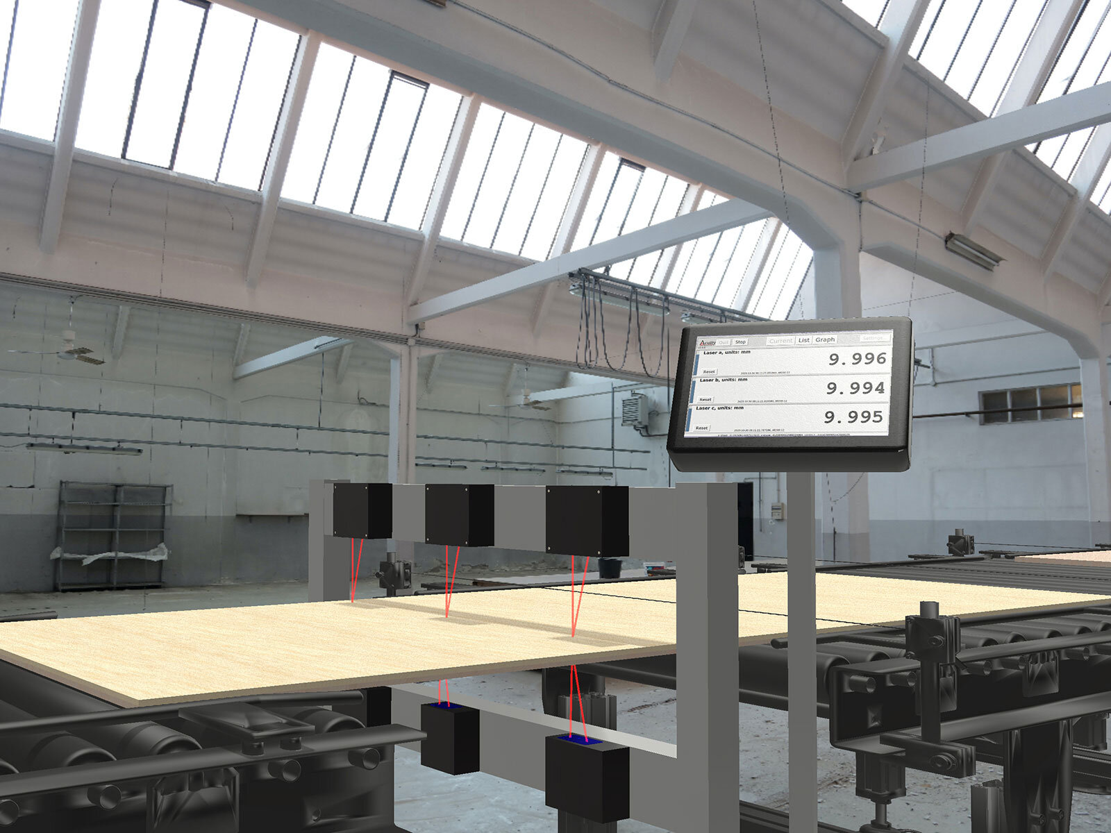
Non-Contact Laser Thickness Measurement for Manufacturing Plywood and Oriented Strand Board
Sawmills are harsh environments for manufacturing plywood and demand accurate laser sensors under dusty conditions. Production of plywood and OSB (oriented strand board) sheets can be highly automated with non-contact sensors. Several Acuity customers are system integrators who develop specialized instruments for the forest products industry.
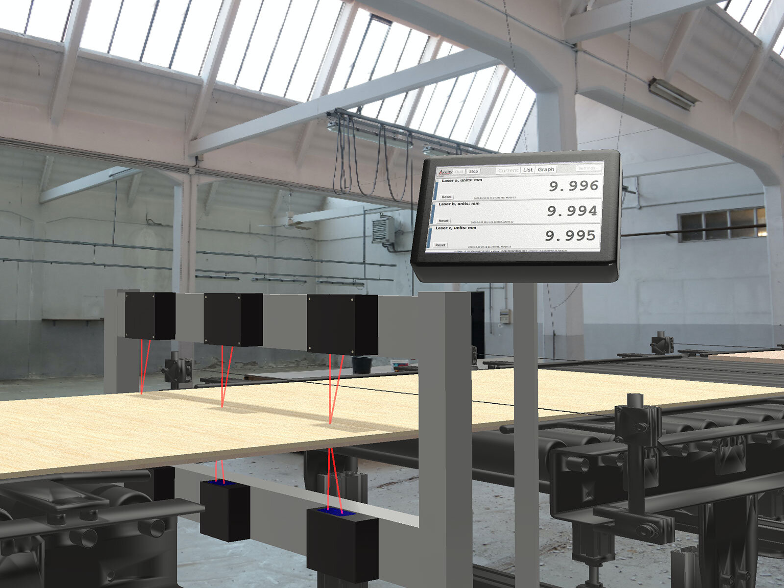
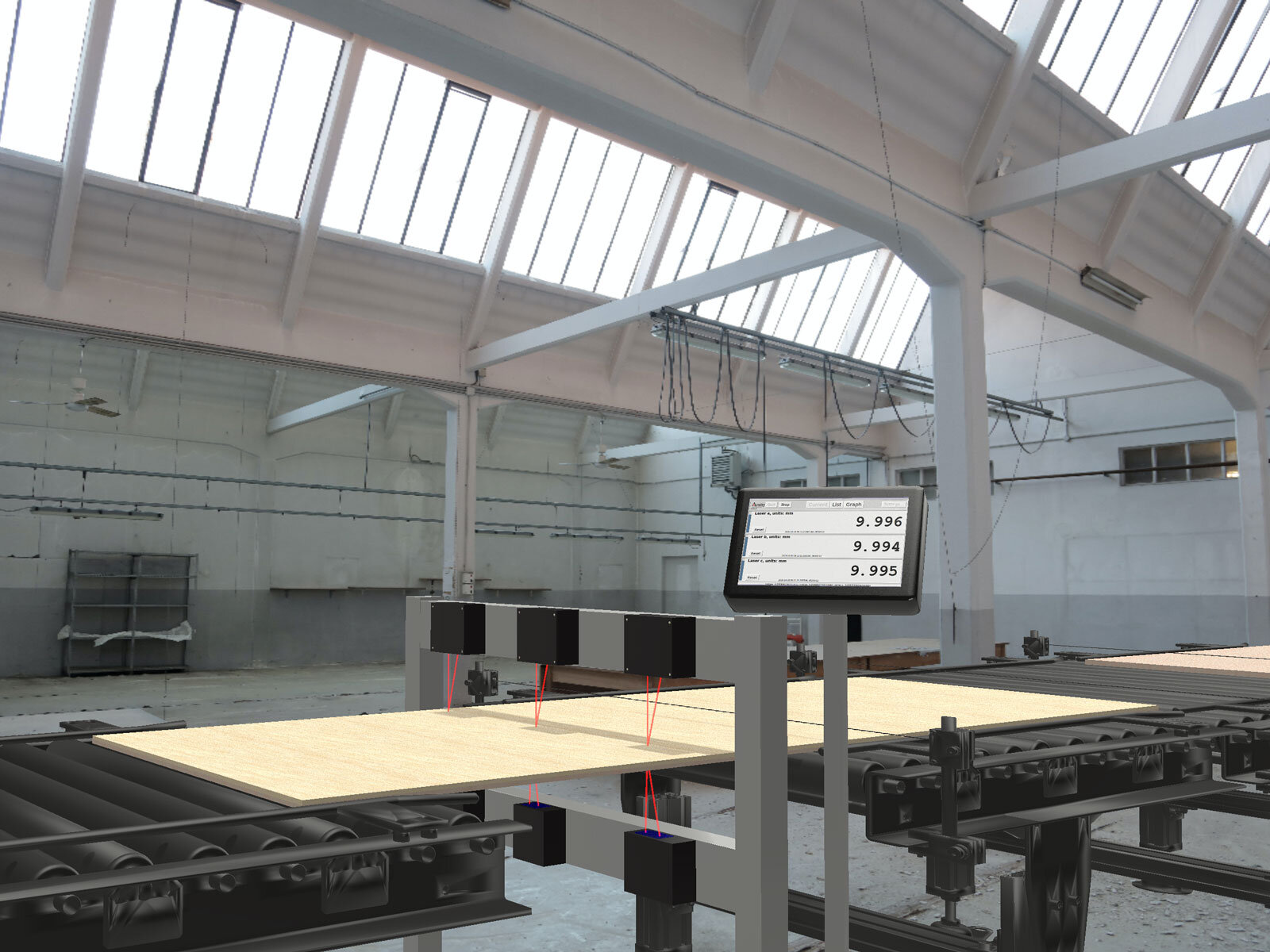
One machine builder chose AR700 laser displacement sensors in opposing pairs to measure dimensions of wood sheets in several locations. The AR700 with a CMOS detector array performs well on plywood, despite the presence of dark-colored knots. Thickness gauging is important because thin boards are inferior and sheets that are too thick waste materials and resources.
Sawmills and plywood manufacturing plants present special challenges because they are dusty environments.
HOW TO USE LASER SENSORS FOR PLYWOOD SHEET THICKNESS MEASUREMENT
If you’re thinking of measuring with laser sensors, let’s look at the specifics of measuring the thickness of a plywood sheet.
As we know, plywood is usually matte, light colored, opaque, and rigid. All of these are perfect conditions for measuring with laser sensors. That said, if it has a clear coat on the surface, that could cause problems with using laser sensor measurement.
Common questions for measuring plywood sheets include:
- What accuracy do I need?
- How many measurements do I need in each direction?
- How often do I need measurements?
Let’s take our plywood sheet and answer those questions. Let’s say the sheets you’re looking to measure are 4 foot by 8 foot and have a thickness of 3/4th of an inch. A typical tolerance is 1/64th of an inch (0.016” or 0.4 mm), but you’ll want an error of at least half that to give room for the error that vibration or other environmental factors might cause. So your margin-for-error might be 0.008”.
In this case, you’re in luck. An AR200-50 has a linearity error of 0.002”, and when used as a pair for measuring thickness, the total linearity error is 0.004”, one half of the error you’re looking for.
CALCULATING FOR PRODUCTION SPEEDS
But now we need to consider how many measurements you need on the plywood sheet. Let’s say the sheets move on a conveyor at a foot per second lengthwise. Previously, using other measurement methods such as contact gauges, workers would pull a sample every hundred sheets or so and measure five-to-ten points on the sheet to verify the thickness. But that’s not very efficient for production, so we’ll use laser sensors instead.
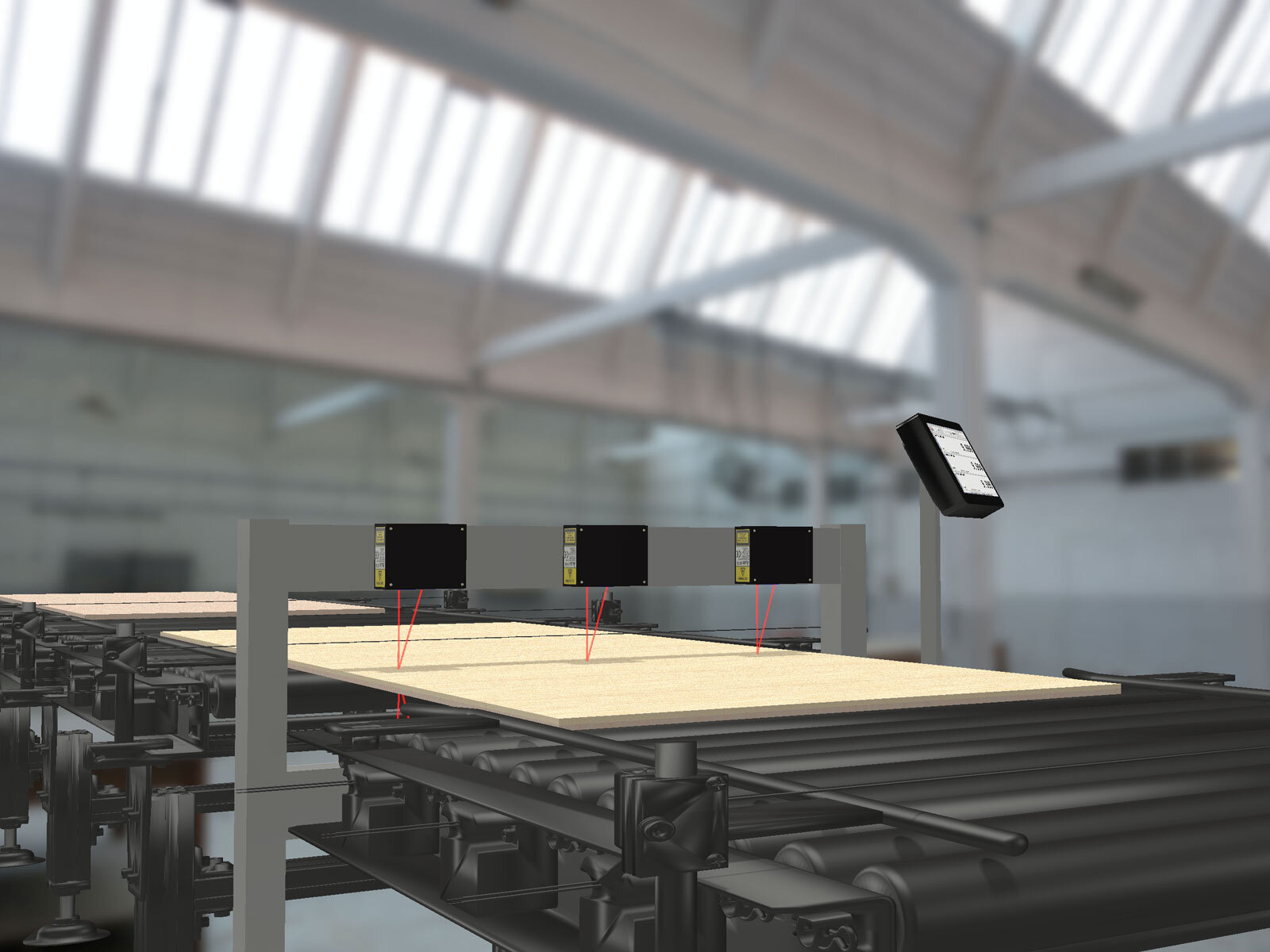
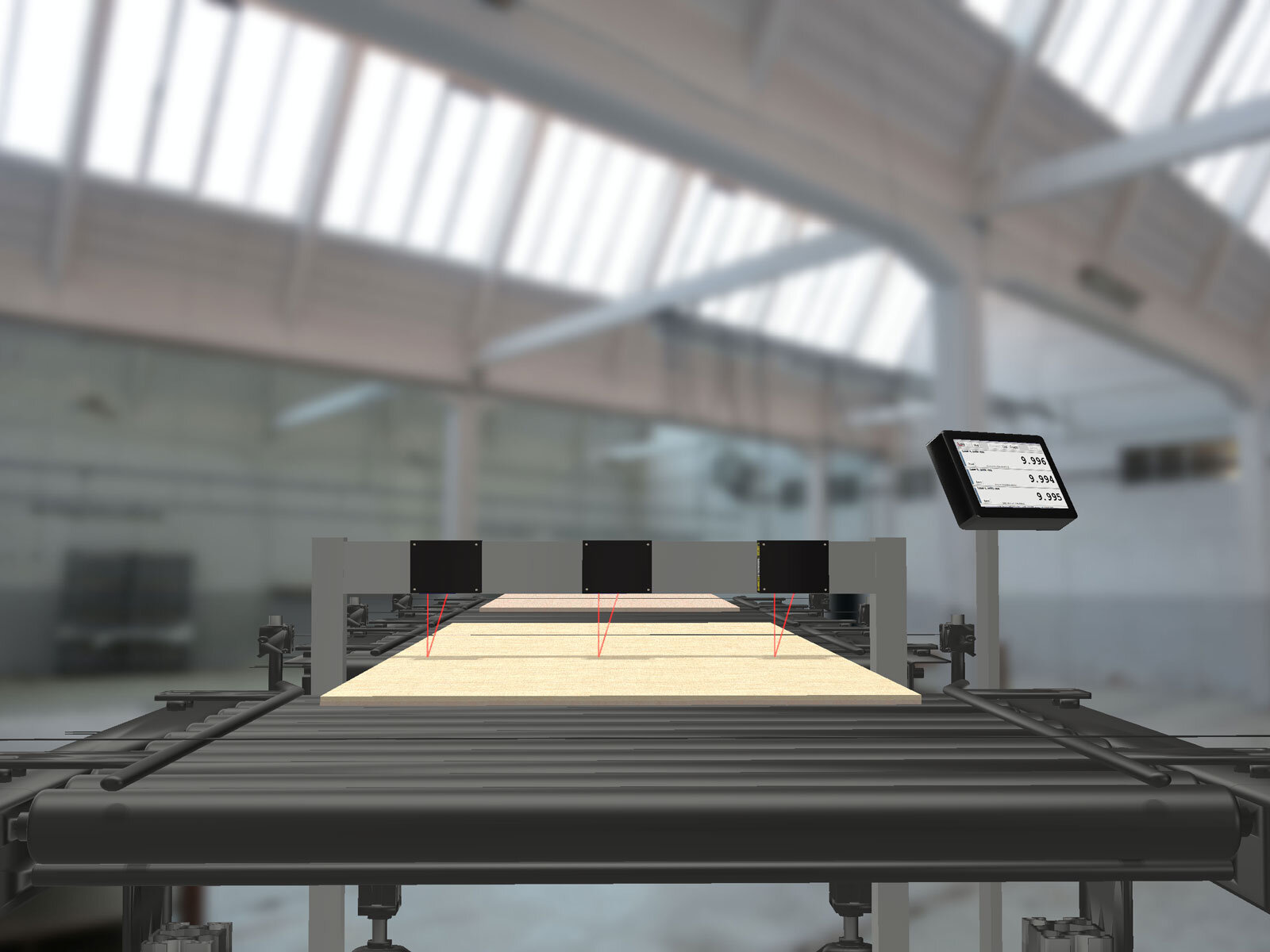
It’s common in plywood manufacturing for the sanding machine to wear out at the edges faster, leaving the board thicker on the outsides. It would be great to measure points all across the width of the board, but that’s resource intensive. If we measured the middle and a little bit inside the two edges as each board passes, we likely would be able to spot trouble. Therefore the best practice would be to measure at three spots across the width of the board.
The boards pass along the conveyor at 1 foot per second. The sanded boards don’t have a lot of pits and grooves, but they can have defects. If you had a measurement every 1/10th of an inch, you’d have plenty of data to iron out insignificant variations while catching the significant ones. So we can calculate that we need a measurement speed of 120 Hz.
Even with its limitations, the AR200 (our most inexpensive sensor) can measure thickness in a dual-sensor setup at 120 Hz. With one pair of sensors for each point, you would need 6 sensors for a 3 point thickness measurement on one production line. So far this is good news!
ENVIRONMENT AND SET UP CONDITIONS
Another aspect to consider is the measurement conditions for your production environment, because often they make your goals more difficult than they look on paper. In many ways, this is the hardest question to evaluate. As you consider your options, the experience of our sales team can be invaluable in helping you determine environmental challenges and find solutions to them.
Acuity sensors measure distance in a number of ways, but every method uses light. Anything that will affect the light at any point between the sensor to the target and back again will affect your measurements. Conditions that obstruct, blur, dim, refract, or reflect the sensor’s light are likely to change the level of performance you can expect from the sensor.
Some common things that can affect the sensor light:
- Dust, either in the air or on the sensor window
- Smoke
- Soot on the sensor window
- Rain, in the air or on the sensor window
- Fog
- Condensation on the sensor window
- Cracks or crevices in the target’s surface (especially for triangulation sensors)
- Clear liquids or solids
- Nearby reflective surfaces that can reflect a second image of a laser spot
- People, birds, bugs, cars… anything that can accidentally move between the sensor and target
MOUNTING THE SENSORS
Finally, you also have to have room to mount the sensors. Many sensors require a specific separation between the sensor and target. The sensors themselves have a case that needs to be accommodated.
In looking at our plywood sheet measurement again, we have to consider what environmental issues could affect the measurements? Let’s run down the list:
- What can affect the laser light?
- Problem: There is dust. The problem is less that a cloud of dust will block the light, but more that the sensor will get dusty over time
- Solution: If the factory has compressed air available, it can be used to blow the dust off the window. If not, a regular cleaning process could be implemented.
- What could cause motion error?
- Problem: The conveyor isn’t very fast, but the boards do bounce up and down a little bit.
- Solution: Synchronization is already very important for thickness applications, but the motion makes it more critical. The AR200 does not have an external trigger wire to trigger measurements, so it can’t be synchronized as precisely. The AR700 might be a better fit, because it does have an external trigger. It’s also more precise, so you would have less motion error with a sensor that has less error altogether.
- Is ambient light a problem?
- Problem: None. The production line is inside, there are no bright lights that would shine directly into the sensor, and the plywood is not on fire, so no issue here.
- Is sensor damage a concern?
- Problem: Not likely. The factory is not temperature controlled, and it can reach 100°F (38°C) inside. This shouldn’t pose a problem. The plywood can bounce around a little bit, but it’s not going to leap an inch or two off the conveyor belt.
- If that were a concern, a longer range sensor can give the target more clearance potentially at the cost of some accuracy. That would be another reason to look at the AR700.
- Is there room to mount the sensors?
- Problem: The conveyor has openings where the sensors can be mounted, but they are relatively narrow, and there needs to be more than 3 inches clearance on the underside of the line.
- Solution: A sensor with a longer range is necessary to get that clearance. Unfortunately, that eliminates the AR200 because that will decrease the accuracy too much, but the AR700 would work just fine!
This isn’t an exhaustive list of potential environmental problems for manufacturing plywood, but it’s something to help you consider using laser sensors for measuring plywood sheet thickness. Should you need technical assistance, the Acuity team is ready to help with your measurement challenges.
Gallery of Plywood Sheet Thickness Gauging


Related Products
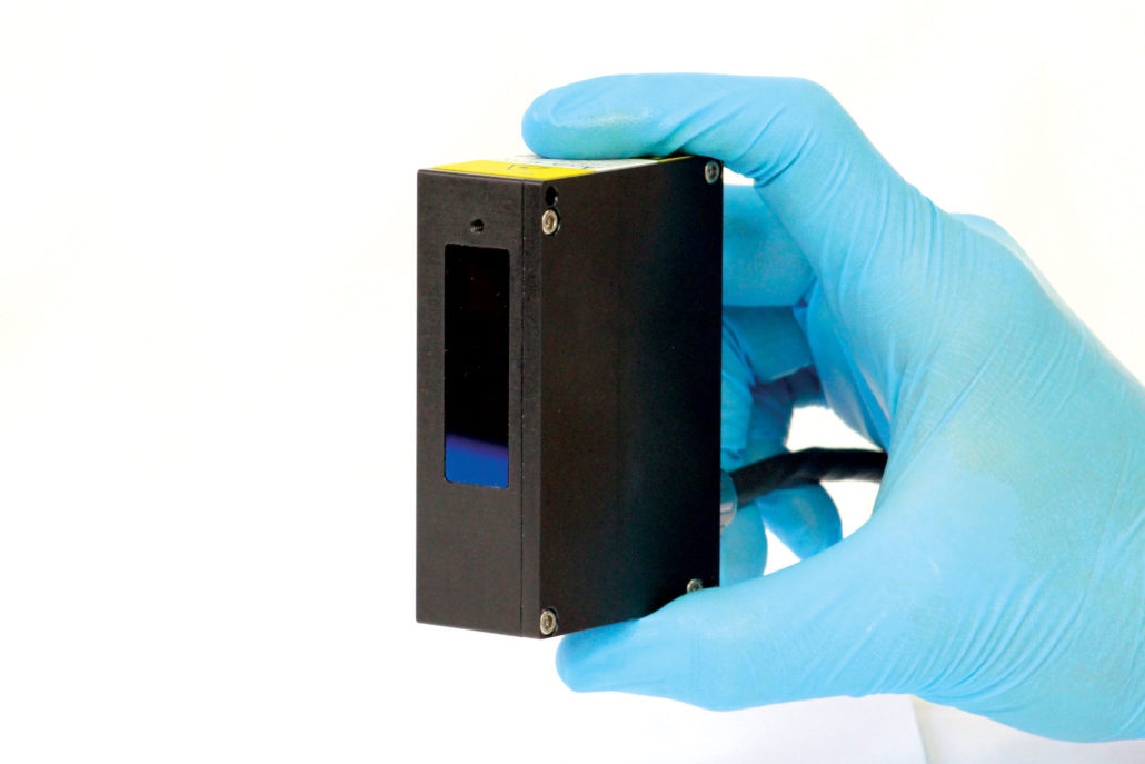
AR700 Laser Displacement Sensor
The AR700 laser displacement sensor is Acuity’s top of the line, most precise, laser triangulation sensor. The AR700 series contains models with measurement ranges from 0.125 inches up to 50 inches and resolutions as low as one-sixth of a micron. With sampling speeds up to 9.4kHz and linearity to within 0.03% of the measurement range, the AR700 is a versatile sensor for many challenging applications.

Sarah has been our technical support and sales engineer for 5+ years. If you've ever reached out to Acuity Laser for tech support, more than likely, Sarah is the one who helped you.